MX vs ATV Supercross
MX vs ATV Steam
MXG-HQ
Reflex Central
MX Maniacs
DirtTwister's Site
Team TD

 
  twisteddirt logo
  Motocross Madness 2

Armadillo track editing tutorial
Displacement mapping: Topographic contour lines.
by mike_mccue


  Have you ever seen a Topographic map similar to this image? The elevations are mapped as contour lines.

  This is a very common mapping technique practiced by government agencies all over the world and consequently many people have developed the skills to read and see the terrain in 3d while viewing this kind of map.

  This tutorial will explain a very quick way to convert any displacement map into a simulated Topographic Map using Photoshop.


  Want more info? You can read all about Topographic mapping at the
United States Geological Survey
website.
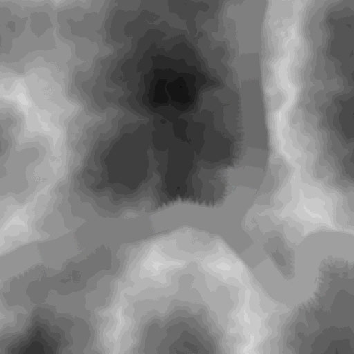


  There are a lot of ways to get started on a new terrain design. You can hand paint something from scratch or use an automated displacement mapping program. Fractal generators are especially interesting as they provide lots of detail with distinctive appearance.

  Here is a fractal image that was generated in Bryce's Terrain Editor at a 512 grid resolution. I have already painted a roadway into it. It has a lot of detail but is also very blurry so its kind of hard to visualize how a trail or manmade features would lay into it.


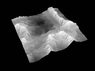
   Here is a 3d render of the displacement map shown above.
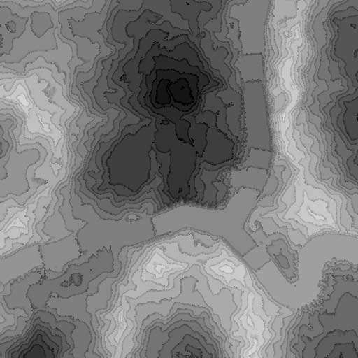


  Here the image has been Posterized with 25 colors.

  Copy the original displacement map to a new layer and choose Image/Adjust/Posterize with 25 colors selected in the dialog box.


  Here is the simulated Topographic Style map. Cool huh?
  Select Filter/Texture/Grain and choose speckle in the pulldown box. Set the contrast and intensity as you wish.
A 0,0 setting was used to make this image.

  If you are familiar with Topographic maps you may find this to be a very helpful visual tool when laying out your tracks.

  Compare your results to real Topographic maps. Imagine how an engineer might work. Look for slopes with parallel contours. (An engineer will usually layout the pathway perpendicular to the most even contours to avoid lots of earthwork expenses.) Identify the natural plateaus in the terrain. Locate the likely spots where erosion will occur. Etc. etc.

 
   Here is a 3d render of the original displacement map with the Topo style map skinned on as a texture. I do not usually take this extra step for my own design work but I thought it would be a fun way to illustrate how useful the Topo style map can be.
    Well, that is it for now. Remember this is a visualization tool that you can use as a reference. The terrain may remain blurry, detailed, rough, smooth.... whatever you prefer.


  This is just one of the many ways I approach track design and
hope you find this tutorial helpful in some way,
mike_mccue

   
      twisteddirt logo